Hidden Line in Engineering Drawing
The technique called section views is a very important aspect of design and documentation. It is used to
- improve the visualization and clarity of new designs,
- clarify multiview drawings,
- reveal interior features of parts, and
- facilitate the dimensioning of drawings.
For mechanical drawings section views are used to reveal interior features of an object when hidden lines cannot properly represent them (e.g., with multiple interior features and excessive overlaying hidden lines). In other words, a primary reason for creating a section view is the elimination of hidden lines.
Architectural drawings use section views to reveal the interior details of walls, ceilings, floors, and other elements of the building structure.
Sectional drawings are multi-view technical drawings that contain special views of a part or parts, which reveal interior features. Sectioning uses a technique that is based on passing an imaginary cutting plane through a part.
In the figure, views a are Standard multiview projections. Views b are Multiview projection with cutting plane placement and Section view. As you can see, the hidden features can be explicitly seen after sectioning.
General principles
- A sectional view represents the part of an object remaining after a portion is assumed to have been cut and removed.
- The exposed cut surface is then indicated by section lines.
- Hidden features behind the cutting plane are omitted, unless required for dimensioning or for definition of the part.
As you can in the figure here the lines of the edges between surfaces on the rear side of the part, shown as hidden lines on the non-cut multiview drawing, disappear from the section view.
Visible surfaces and edges that represent a change of planes or surfaces behind the cutting plane are drawn in a section view:
All hidden lines behind the cutting plane must not be shown, but all visible lines should be shown!
Section lines and symbols
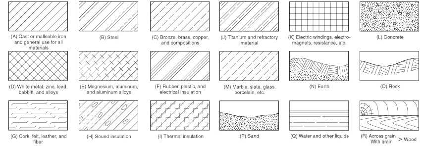
Section lines, or hatching, that represent the cut surface usually consist of thin parallel lines, as shown below, drawn at an angle of approximately 45° to the principal edges or axes of the part.
For most purposes, the general use symbol of cast iron is used. When it is desired to indicate differences in materials, for example on assembly drawings involving a variety of materials, other symbolic section lines may be used.
If the section lines appear to be parallel, or nearly so, to one of the sides or features of the part, you should choose other than 45 0 angle. Section lines should not run parallel or perpendicular to the visible outline.
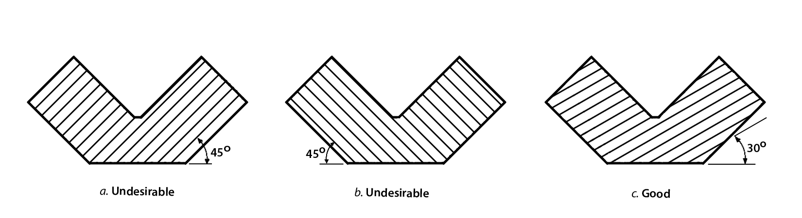
The general purpose or cast iron section line is drawn at a 450 angle and spaced 1/16" (1.5mm) to 1/8" (3mm) or more depending on the size of the drawing.
- In all sections of a single component, section lines should be similar in direction and spacing, but adjacent parts should be section-lined in different directions, angles, or spacing.
- Section lines should be thinner than visible lines.
- Do not run section lines beyond the visible outlines or stop them too short.
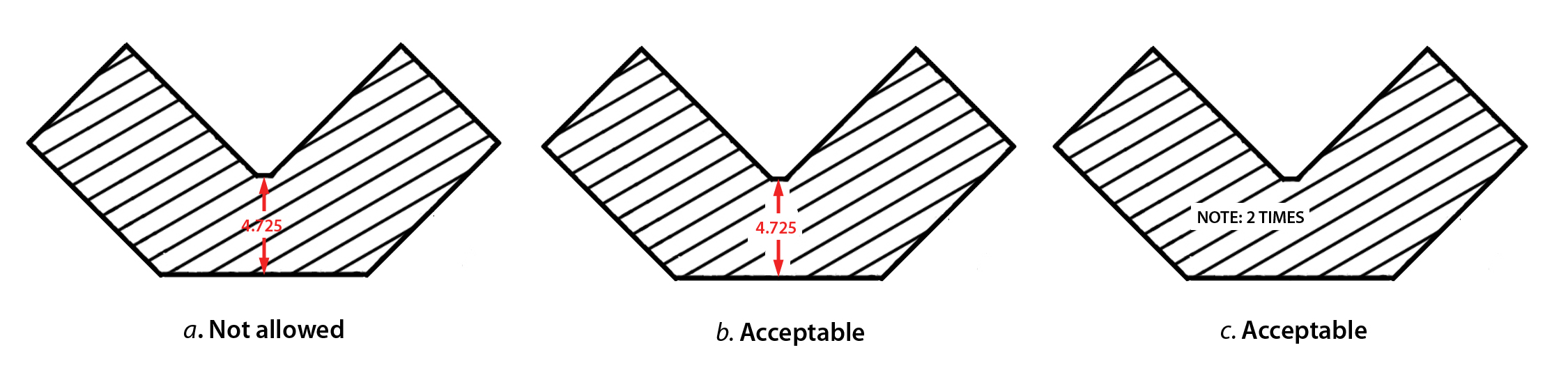
- Section lines should be suitably spaced in relation to the size of the area covered, and for large areas it is recommended that section lines be shown only along the edges.

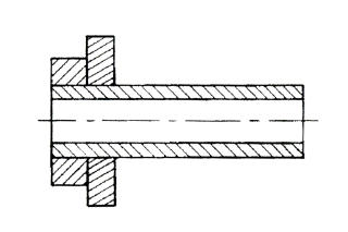
- Thin elements should not be sectioned.
Avoid placing dimensions or notes within the section-lined areas. However, where the insertion of dimensions or lettering in sectional areas is unavoidable, omit the section lines in the area of the note.
Cutting planes
Cutting plane lines which show where the cutting plane passes through the object, represent the edge view of the cutting plane and are drawn in the view(s) adjacent to the section view.
Here the cutting plane is drawn as an edge in the top view, which is adjacent to the sectioned front view. This is a frontal cutting plane. Lines of sight should always be directed upwards on the top view for sectioned front view.
A horizontal cutting plane is one where it is an edge in the front view and the top view is sectioned.
If the cutting plane appears as an edge in the top and front views and the profile view is sectioned, it is a profile cutting plane.
In the drawing you must show the cutting plane line either on front view (with the top sectioned view) or on top view (with the frontal section view), not on both.
Two types of lines are acceptable for cutting plane lines in multi-view drawings. Position of the line-of-sight arrows also can vary. But it is important to use only one type of cutting plane line in a single drawing.
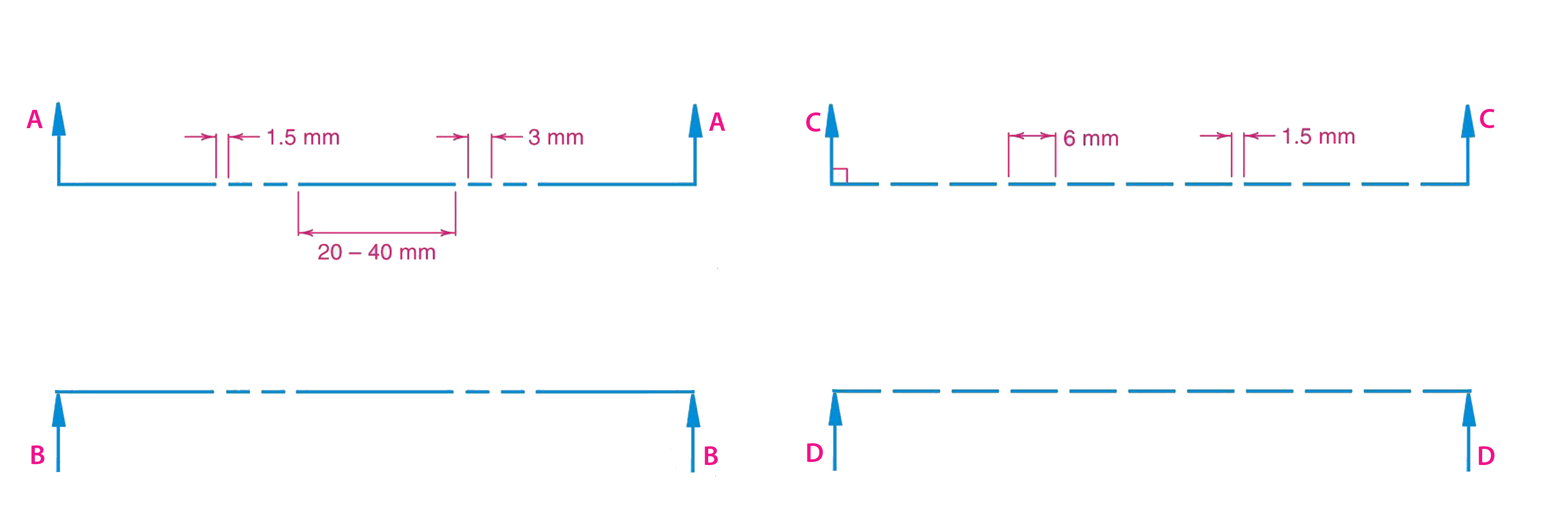
Cutting plane lines are thick (0.6 mm) dashed lines, that extend past the edge of the object 6mm (1/4") and have line segments at each end drawn at 90 degrees and terminated with arrows. The arrows represent the direction of the line of sight for the section view and they point away from the sectioned view.
The long dash can be lengthened for large section drawings to save time and create a more readable drawing.
Multiple sections can be done on a single object.
Cutting planes shall not be shown on sectional views.
To include features that are not in a straight line, the cutting plane may be offset or bent at one or more 900 angles, to include several planes or curved surfaces. It is called offset section and is used for complex parts that have several important features that cannot be sectioned using a straight cutting plane.
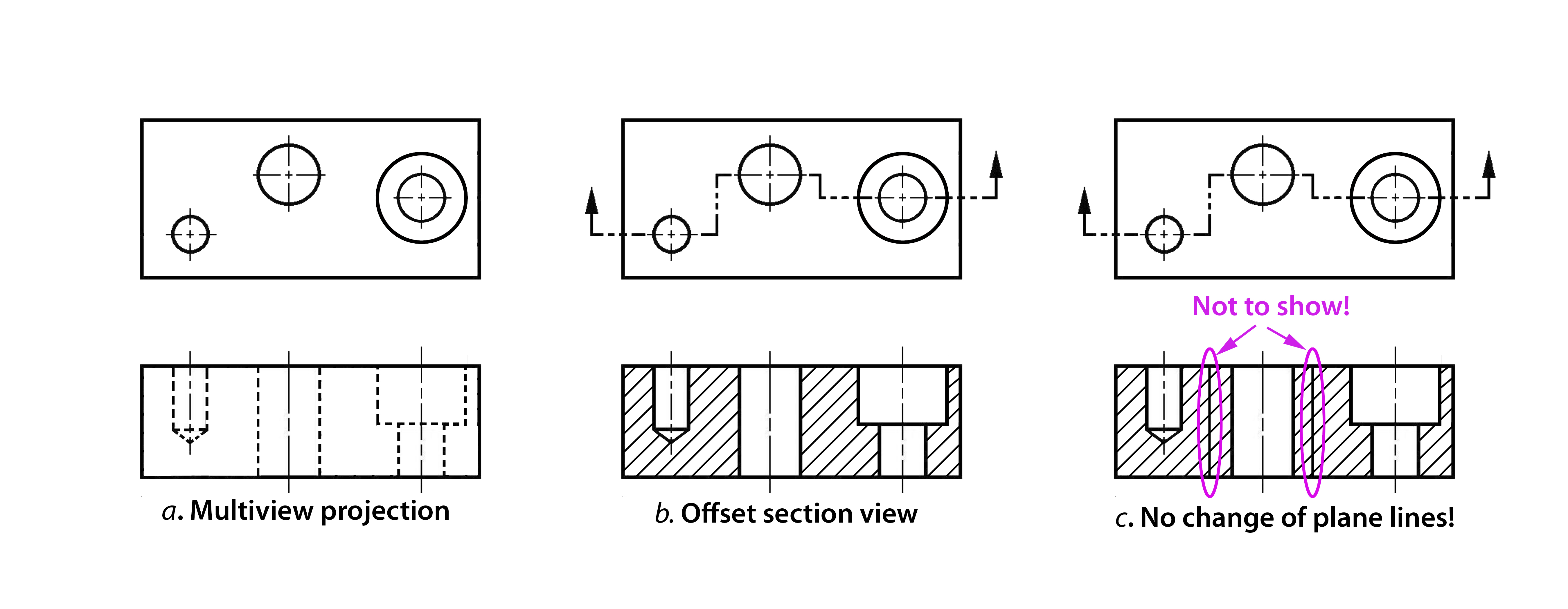
The change of plane that occurs when the cutting plane is bent at 900 is not represented with lines in the section view !
Sometimes it is not necessary to cut the whole part to show the section view. Objects that are symmetrical about a centre line you may draw having one half as a multiview and the other half in section view. In such situation
- Cutting plane line is shown across the whole part;
- Section plane through center line of a symmetric part can be omitted;
- Hidden lines in half sections are usually omitted.
Again: In case of half sections, if there are hidden feature lines corresponding to full lines in the sectioned half, such hidden lines should be omitted from the full view. In this sense, the drawing shown here is not correct, since the hidden lines are shown on the sectioned part of the view. They should have been omitted!
In some cases it is more convenient to use a partial section.

A broken-out section is used when only a portion of the object needs to be sectioned. The following figure shows a part with a portion removed or broken away.

A broken-out section is used instead of a half- or full-section view to save time, and a break line is drawn freehand to represent the jagged edge of the break.
There is one more type of sections which may be useful to know. Revolved section is made by revolving the cross section view of a feature 90° about an axis of revolution and superimposing the section view on the orthographic view.
If the revolved section view does not interfere or create confusion on the view, then the revolved section is drawn directly on the view using visible lines, as shown in the view b of the figure. When the revolved view is superimposed on the part, the original lines of the part behind the section are deleted. If the revolved section crosses lines of the view on which it is to be revolved, then the view can be broken for clarity, as you can see in view c.
The shape of the cross-section of a bar, arm, spoke, or other elongated object may be shown by means of a revolved section.
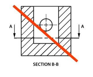
Thin wall sections. Ribs, webs, spokes, gear teeth and other thin features are not section lined when the cutting plane passes parallel to the feature. Adding section lines to these features would give the false impression that the part is thicker than it really is. In the figure you can see cutting planes that pass parallel to and through the web.
Leaving thin feature unsectioned only applies if the cutting plane passes parallel to the feature (SECTION A-A). If the cutting plane passes perpendicular or crosswise to the feature (SECTION B-B), section lines are added.
Main Principles of Placement of Sectional Views
- Whenever practicable, and except for revolved sections, you should project sectional views perpendicular to the cutting plane and place it in the normal position for third angle projection.
- You should never show the views in first angle projected position on a third angle projection drawing.
- When the preferred placement is not practical you may remove the sectional view to some other convenient position on the drawing, but it must be clearly identified, usually by two capital letters, excluding I, O, Q, and Z, and be labelled.
- Normally, you should not change orientation of the view, but if this becomes necessary, you must state the number of degrees through which it is revolved.
Source: https://www.mcgill.ca/engineeringdesign/step-step-design-process/basics-graphics-communication/sectioning-technique
0 Response to "Hidden Line in Engineering Drawing"
Post a Comment